Advanced Driver for Dimmable LED Lighting
Ali Imam Khan
Abstract. With the rapid development in high brightness light-emitting diode (LED) technologies, both in the performance and the cost, white LED (WLED) have improved significantly. Due to its high efficacy, long life, and very low maintenance requirement, WLED is more and more accepted in general lighting applications LEDs are current-driven devices. A driver circuit is proposed in this paper to drive LEDs at a required constant current. The driver circuit used a dc link voltage Source and a fly back converter. Theoretically, only a trivial current is generated on an LED when the forward voltage is lower than its cut-in voltage. Beyond the threshold, a mall variation in the forward voltage results in a significant change in the LED current. The dimming feature is controlled by Pulse-Width modulation instead of Double pulse-width modulation (DPWM).
Keywords: Light Emitting Diode (LED), phosphor-converted White LED (WLED), efficacy (light output per watt), Pulse-Width Modulation (PWM), Continuous-Conduction Mode (CCM), Discontinuous Conduction Mode (DCM).
1 Introduction
A Light Emitting Diode (LED) [1] is an electronic device that produces light when an electrical current is passed through it. The wavelength (or colour) of light that is emitted is dependent on the materials from which the LED is made. Due to its high efficacy, long life, and very low maintenance requirement, WLED is more and more accepted in general lighting applications [2]. The increased interest in LEDs has challenged electronic engineers to stretch up with efficient and cost-effective solutions in the plan of the driver [3] circuits. Till now, a mostly used high brightness white LED [4] is rated at 1 W, which is driven at 350 mA. LEDs are current-driven devices [5]. Conventionally, driving a string of high brightness LEDs at an accurate dc current typically resorts to a linear regulator or a more complicated switching regulator with sophisticated control, especially when a dimming function is included[6]-[11].
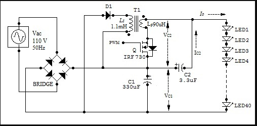
To improve the overall efficiency of LED lighting, an efficient driver is proposed in this paper. The operating characteristic of an LED is shown in Fig.2. Above the threshold, a mall variation in the forward voltage results in a significant change in the LED current. The proposed LED driver circuit shows in Fig.2, in which a string of LEDs are driven by two sources: one for providing the cut-in voltage and the other for regulating the forward current. In practice, the cut-in voltage is much higher than that for current regulation. In such a configuration, the dc voltage source for cutting in LED linear operation supplies the majority of the LED power directly, while only a small amount of power has to be processed for current regulation, leading to high overall efficiency. [12]-[15]

2 Circuit Descriptions
The Proposed LED driver circuit shows in the Fig-2 consist with three main sections (i) DC Voltage Source. (ii) PWM Generator (iii) LED Stack, (iv) Fly-back Converter[16] and (v) Control Switch Q
2.1 PWM Generator
PWM generator is used to generate control signal to Switch Q. By changing the duty ratio of the PWM, output voltage will change.
2.2 DC Voltage Source
Fig. 2. Proposed LED driver circuit The DC-link voltage source VC1 can be obtained from the AC mains through a diode bridge rectifier. A fly-back converter functioning as a current regulator is interposed between the dc link and the LED lamp. Instead of being powered by a fly-back converter, the LED lamp is supplied from the fly-back converter in series with a virtual voltage source of the dc-link.
2.3 LED Stack
40 numbers of 1Watt LEDs are connected to form a LED stack to produce light output.
2.4 The Fly-Back Converter
The fly-back converter is formed by an active power switch Q, a coupled inductor, and a freewheeling diode D. The primary side of the coupled inductor Lp is associated with a filter capacitor C2, while the secondary Ls is connected to the dc-link capacitor C1. Consequently, the LED lamp is driven by the sum of the voltages on C1 and C2, which are with opposite polarities. To provide a forward voltage to the LED lamp, the dc-link voltage has to be slightly higher than the cut-in voltage of the LEDs in series, but much higher than the voltage on C2. With such a configuration, the LED lamp is driven by the dc-link voltage in series with the fly-back converter, which plays the role of the current regulator. Then, the lamp current can be regulated by adjusting the duty ratio of the fly-back converter.
2.5 Control Switch Q
A MOSFET is used in Common Low Side Configuration to act as control switch.
3 Circuit Operation
The fly-back converter in the driver circuit can be operated at the continuous-conduction/flux mode (CCM) or the Discontinuous Conduction/flux Mode (DCM). To achieve a smaller coupled inductor and less switching loss, the proposed circuit is designed to be operated with DCM.
The operation of the power conversion circuit can be divided into three stages for DCM. The equivalent circuits and the current flows for the three operation stages are shown in Figures. The LED lamp is represented by the cut-in voltage Vf of the LEDs connected in series with an equivalent resistance Re accounting for the conduction losses. Fig. 3 depicts the theoretical waveforms on key components.
Stage I: Stage I begins when the active power switch Q is switched ON. In this stage, the diode D is reverse-biased. A nearly constant voltage on the capacitor C2 is applied to the primary of the coupled inductor. The inductor current ip rises up linearly. Meanwhile, the dc-link delivers power through the filter capacitor C2 to the LED lamp. Stage I ends when Q is switched OFF
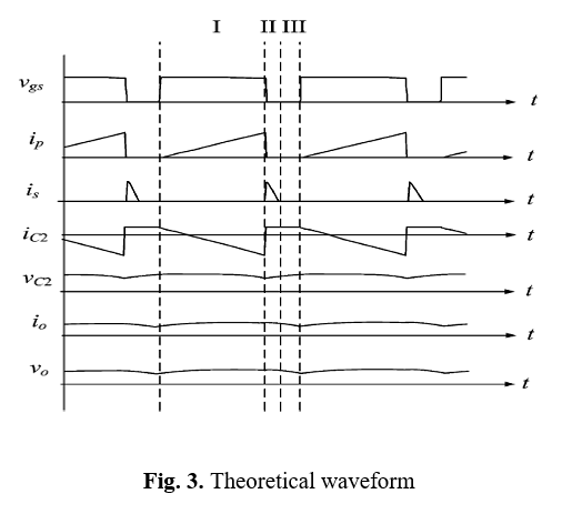
Stage II: As Q is switched OFF in Stage II, the diode D is forward biased to conduct the freewheeling current. During this stage, the secondary side of the coupled inductor returns the stored energy to C1 . The dc-link continues to supply the lamp power through the filter capacitor C2 . At the same time, the dc-link voltage on the inductor results in a decrease in its current. Stage II ends when the inductor current is declines to zero.
Stage III: During this stage, both Q and D are turned OFF. The LED lamp draws a current from C1 and C2 continuously. The operation returns to Stage I when the power switch Q is switched ON again in the next high-frequency cycle. It should be noted that C2 is charged by the output current when Q is turned OFF. In the case that Q has been turned OFF for a long interval, C2 will be charged up to a relatively high voltage. As a result, the LEDs will be cut off.
4 Circuit Analysis
The The voltage applied to LEDs is equal to the dc-link voltage with a subtraction of the voltage on C2

LED lamp can be denoted by the cut-in voltage VF in series with the resistance Re, the voltage on the lamp can be expressed as

where Io is the lamp current. The lamp current is represented as

During Stage I, the inductor current ip rises up linearly from zero, and reaches its peak at the end of the stage. The peak current Ipp can be obtained as

d and Ts are the duty ratio and the switching period of the fly-back converter, respectively. Since C2 is charged and discharged by io and ip, respectively, the charge flowing into and out of the capacitor should be balanced at the steady state.

Substituting (3) and (4) into (5) yields

Then, the lamp current is calculated as

Consequently, Vo is obtained as

From Equations (7) and (8) indicate that the output voltage and hence the lamp current can be regulated by controlling the duty ratio of the fly-back converter.
5 Dimming Technique
The brightness of an LED is approximately proportional to its average current. Pulse Width Modulation (PWM) on the LED current can be used for dimming control. But large firing angle, LED Lamp could flicker easily at the frequency of 100 or 120 KHz, namely invisible flicker. Although the invisible flicker cannot be easily seen by human eyes, it will cause possible health problems, like brain damaging, headaches, eye strain and so on [17]. With the proposed driver, the PWM dimming can be realized simply by adjusting the duty ratio of a high frequency PWM in the fly-back converter.
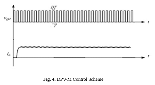
The switch Q is gated by a signal which is a of a high frequency gating signal VgH . With PWM dimming, the fly-back is switched OFF and ON during the PWM signal. In this case, VC2 will be charged up until the LED lamp cuts off. The lamp remains at the cut-off state during the turn-off interval of Q, and is lighted up again while Q is switched ON at the next cycle. Consequently, the LED lamp can be driven by a pulsed current. The magnitude of the pulse current is modulated by the high-frequency PWM.
Pulse-width modulation dimming actually turns the LEDs on and off at a fixed duty cycle and frequency. Assuming the switching or multiplexing is sufficiently fast – typically 200 Hz or greater – the human eye perceives the LEDs to be on continuously. The PWM-dimmed LED current is determined by the following equation:
Where IDIM is the dimmed LED current, D is the on duty cycle of the PWM dimming signal, and ILED is the constant current supplied to the switched LED string.
6 Results
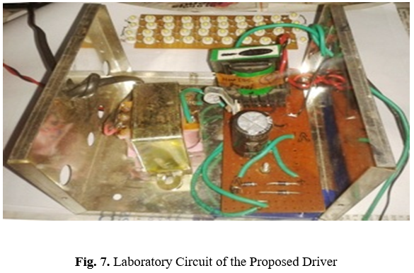
A prototype of the driver is designed and tested for a 40 numbers of 1W LED in series supplied from an ac input voltage of 110 V at a frequency of 70 KHz.
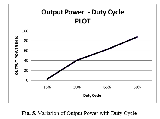
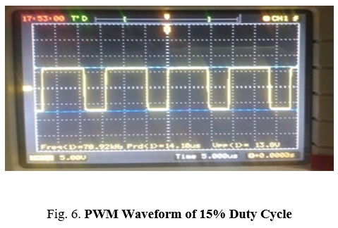
The fly-back converter is designed to be operated with CCM at a high frequency of 70 KHz for PWM dimming. To avoid visible flickers, the dimming frequency is designated below 100 Hz. The LED current can be regulated from 10 mA to the rated current of 250 mA by adjusting the duty ratio of the high-frequency PWM from 15% to 80% as shown by Fig. 4 and Table 1. Fig. 5 shows the Pulse waveforms to the gate of the MOSFET in the fly-back converter at a high frequency.
Acknowledgement
I feel proud to express my profound a deep gratitude to my respected teachers of Electronics and Communication Engineering Department for helping me. Their valuable assistant and constant guidance through the work was constant source of inspiration without which it would have been difficult for me to continue the project.
References
- Holonyak Nick; Bevacqua, S. F. (December 1962).“Coherent (Visible) Light Emission from Ga(As1−x Px) Junctions”. Applied Physics Letters 1 (4): 82.
- Junming Zhang, Member, IEEE, Hulong Zeng, and Ting Jiang, A Primary-Side Control Scheme for High-Power-Factor LED Driver With TRIAC Dimming Capability, in IEEE Tranc On Power Electronics, Vol. 27, No. 11, November 2012
- Y. C. Li and C. L. Chen, “A novel single-stage high-power-factor AC-to-DC LED driving circuit with leakage inductance energy recycling,” IEEE Trans. Ind. Electron., vol. 59, no. 2, pp. 793–802, Feb. 2012.
- 2006 Millennium technology prize awarded to UCSB’s Shuji Nakamura. Ia.ucsb.edu (June 15, 2006). Retrieved on March 16, 2012.
- Maxim, “Why drive white LEDs with constant current,” Sunnyvale, CA, U.S. Aug. 2004
- Chin-Sien Moo, Member, IEEE, Yu-Jen Chen, Student Member, IEEE, and Wen-Ching Yang, “An Efficient Driver for Dimmable LED Lighting”, in IEEE Transactions On Power Electronics, Vol. 27, No. 11, November 2012
- D. Rand, B. Lehman, and A. Shteynberg, “Issues,models and solutions for TRIAC modulated phase dimming of LED lamps,” in Proc. IEEE Power Electron. Spec. Conf., 2007, pp. 1398–1404
- Ruihong Zhang and Henry Shu-Hung Chung, “ATRIAC-Dimmable LED Lamp Driver With Wide Dimming Controle”. IEEE Transactions On Power Electronics, Vol. 29, No. 3, MARCH 2014
- Lutron Electronics Co. “Controlling LEDs”, http://www.lutron.com/Technical Document Library/367-2035_LED_white_paper.pdf
- Ethan Biery, “Matching SSL and Control technology remains a Challange” http://www.ledsmagazine.com/content/dam/leds/past-issues/2013/07/1307LEDS.pdf, page-27-32
- David Zhang, “Dimming Multiple LED string enables colour tenable Iuminaires” http://www.ledsmagazine.com/content/dam/leds/past-issues/2013/07/1307LEDS.pdf, page-57-58
- E. M. Sa, F. L. M. Antunes, and A. J. Perin, “Low cost self-oscillating ZVS-CV driver for power LEDs,” in Proc. IEEE Power Electron. Spec. Conf., Jun. 2008, pp. 4196–4201.
- K. B. Park, C . E. Kim, G . W. Moon, and M . J. Youn, “Non-isolated high step-up converter based on boost integrated half-bridge converter,” in Proc. Int. Telecommun. Energy Conf., Oct. 2009, pp. 1–6
- D. Gacio, J. M. Alonso, A. J. Calleja, J. Garcia, and M. Rico-Secades,“A universal-input single-stage high-power-factor power supply for HBLEDs based on integrated buck-flyback converter,” IEEE Trans. Ind.Electron., vol. 58, no. 2, pp. 589–599, Feb. 2011
- K. I. Hwu, Y. T. Yau, and L. L. Lee, “Powering LED using high-efficiency SR flyback converter,” IEEE Trans. Ind. Appl., vol. 47, no. 1, pp. 376–386, Jan. 2011
- DC to DC Converters, Flyback Converter ((Ee)Nptel), Version 2 EE IIT, Kharagpur,
- Ruihong Zhang and Henry Shu-Hung Chung, “ATRIAC-Dimmable LED Lamp Driver With Wide Dimming Controle”. IEEE Transactions On Power Electronics, Vol. 29, No. 3, MARCH 2014